Design Discussion
Overview
In CCSM3/cpl6, all components ran as separate executables and there was no concept of a top-level driver. The components started independently and then communicated to the coupler at regular intervals via send and receive methods called directly from within each component. The coupler acted as a central hub coordinating data exchange, implicitly managing lags and sequencing, and executing coupler operations such as mapping (interpolation) and merging.
CESM1/cpl7 is now built as a single executable with a single high-level driver. The driver runs on all processors and handles coupler sequencing, model concurrency, and communication of data between components. The driver calls all model components via common and standard interfaces. The driver also directly calls coupler methods for mapping (interpolation), rearranging, merging, an atmosphere/ocean flux calculation, and diagnostics. In CESM1, the model components and the coupler methods can run on subsets of all the processors. In some sense, the cpl6 sequencing and hub attributes have been migrated to the driver level while the cpl6 coupler operations like mapping and merging are being done as if a separate coupler component existed in CESM1. In other words, cpl7 consists of a driver that controls the top level sequencing, the processor decomposition, and communication to components through subroutine calls while coupler operations such as mapping and merging are running under the driver on a subset of processors as if there were a unique coupler model component.
CESM1 consists of both data and active components models. In general, an active component both needs data from and provides data to the coupler while data models generally read data from I/O and then just provide data to the coupler. In CESM1, like CCSM3, the atmosphere, land, and sea ice models are always tightly coupled to better resolve the diurnal cycle. This coupling is typically half-hourly, although at higher resolutions, coupling can be more frequent. The ocean model coupling is typically once or a few times per day. The diurnal cycle of ocean surface albedo is computed in the coupler for use by the atmosphere model. The looser ocean coupling frequency means the ocean forcing and response is lagged in the system. There is an option in CESM1 to run the ocean tightly coupled without any lags, but this is normally used only when running with data ocean components.
Depending on the resolution, hardware, run length and physics, a CESM1 run can take several hours to several months of wall time to complete. Runs are typically decades or centuries long, and the model typically runs between 1 and 50 model years per wall clock day. CESM1 has exact restart capability and the model is typically run in individual one year or multi-year chunks. CESM1 has automatic resubmission and automatic data archiving capability.
Sequencing and Concurrency
In CESM1, the component processor layouts and MPI communicators are derived from namelist input. At the present time, there are seven (7) basic processor groups in CESM. These are associated with the atmosphere, land, ocean, sea ice, land ice, coupler, and global groups, although others could be easily added later. Each of the seven processor groups can be distinct, but that is not a requirement of the system. A user can overlap processor groups relatively arbitrarily. If all processors sets overlap each other in at least one processor, then the model runs sequentially. If all processor sets are distinct, the model runs concurrently. The processor sets for each component group are described via 3 basic scalar parameters at the present time; the number of mpi tasks, the number of openmp threads per mpi task, and the global mpi task rank of the root mpi task for that group. For example, a layout where the number of mpi tasks is 8, the number of threads per mpi task is 4, and the root mpi task is 16 would create a processor group that consisted of 32 hardware processors, starting on global mpi task number 16 and it would contain 8 mpi tasks. The global group would have at least 24 tasks and at least 48 hardware processors. The driver derives all MPI communicators at initialization and passes them to the component models for use.
As mentioned above, there are two issues related to whether the component models run concurrently. The first is whether unique chunks of work are running on distinct processor sets. The second is the sequencing of this work in the driver. As much as possible, the CESM1 driver sequencing has been implemented to maximize the potential amount of concurrency of work between different components. Ideally, in a single coupling step, the forcing for all models would be computed first, the models could then all run concurrently, and then the driver would advance. However, scientific requirements such as the coordination of surface albedo and atmosphere radiation computations as well as general computational stability issues in CESM1 prevent this ideal implementation. Figure 1 shows the maximum amount of concurrency supported by the current CESM1 driver implementation for a fully active system. In practice, the scientific constraints mean the active atmosphere model cannot run concurrently with the land and sea-ice models. Again, figure 1 does not necessarily represent the optimum processor layout for performance for any configuration, but it provides a practical limit to the amount of concurrency in the system due to scientific constraints. With CESM1, results are bit-for-bit identical regardless of the component sequencing because the scientific lags are fixed in CESM1 by the implementation, not the processor layout.
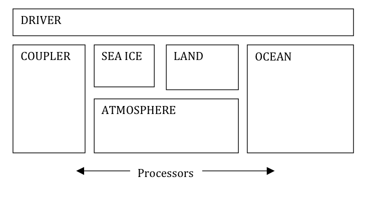
Figure 1: Maximum potential processor concurrency designed into CESM1 to support scientific requirements and stability.
Relative to CCSM3, there is a loss of concurrency in CESM1 because they are coupled in fundamentally different ways. In CESM1, the model run methods are called from the driver and the coupling from the overall system perspective looks like "send to component, run component, receive from component". In CCSM3, the coupling was done via calls inside each component and the data send and receive could be interleaved with work such that the model run method appeared to have two phases, one between the coupling send and receive, the other between the receive and send. That allowed greater concurrency in CCSM3, but was designed for concurrent-only coupling. In CESM1, we chose not to implement multiple run phases in order to simplify the model and provide an opportunity for greater interoperability. This choice was made with the full understanding that there would be some potential loss of model concurrency in specific cases. Designers felt the additional flexibility of allowing models to run in a mixed sequential/concurrent system would likely overcome any performance degradation associated with a loss of concurrency.
Component Interfaces
The standard CESM1 component model interfaces are based upon the ESMF design. Each component provides an init, run, and finalize method with consistent arguments. The CESM1 component interface arguments currently consist of Fortran and MCT datatypes, but an alternative ESMF version is also available. The physical coupling fields are passed through the interfaces in the init, run, and finalize phases. As part of initialization, an MPI communicator is passed from the driver to the component, and grid and decomposition information is passed from the component back to the driver. The driver/coupler acquires all information about resolution, configurations, and processor layout at run-time from either namelist or from communication with components.
Initialization of the system in CESM1 is relatively straight-forward. First, the seven MPI communicators are computed in the driver. Then the atmosphere, land, ocean, sea ice, and land ice models' initialization methods are called on the appropriate processor sets, and mpi communicator is sent, and grid and decomposition information are passed back to the driver. Once the driver has all the grid and decomposition information from the components, various rearrangers and mappers are initialized that will move data between processors, decompositions, and grids as needed at the driver level. No distinction is made in the coupler implementation for sequential versus concurrent execution. In general, even for cases where two components have identical grids and processor layouts, often their decomposition is different for performance reasons. In cases where the grid, decomposition, and processor layout are identical between components, the mapping or rearranging operation will degenerate to a local data copy.
The interface to the components' run method consists of two distinct bundles of fields. One is the data sent to force the model. The second is data received from the model for coupling to other components. The run interface also contains a clock that specifies the current time and the run length for the model. These interfaces follow the ESMF design principles.
MCT, The Model Coupling Toolkit
MCT was a critical piece of software in the CCSM3 cpl6 coupler. In the updated CESM1 cpl7 coupler, the MCT attribute_vector, global_segmap, and general_grid datatypes have been adopted at the highest levels of the driver, and they are used directly in the component init, run, and finalize interfaces. In addition, MCT is used for all data rearranging and mapping (interpolation). The clock used by CESM1 at the driver level is based on the ESMF specification. Mapping weights are still generated off-line using the SCRIP package as a preprocessing step. They are read into CESM1 using a subroutine that reads and distributes the mapping weights in reasonably small chunks to minimize the memory footprint. Development of the CESM1 cpl7 coupler not only relies on MCT, but MCT developers contributed significantly to the design and implementation of the cpl7 driver. Development of both the cpl6 and cpl7 coupler has resulted from a particularly strong and close collaboration between NCAR and the Department of Energy Argonne National Lab.
Memory, Parallel IO, and Performance
CESM1 is targeting much higher resolutions than any previous CCSM coupled model. In order to facilitate scientific climate model exploration and development at these scales, the technology had to be put in place first to enable testing of this case. Efforts have been made to reduce the memory footprint and improve memory scaling in all components with a target of being able to run the fully coupled system at one tenth (0.1) degree resolution globally on tens-of-thousands of processors with each processor having as little as 512 Mb of memory. This target limits the number of global arrays that can be allocated on any processor to just a few, at most, at any time. The memory limitations have imposed new constraints on component model initialization, and significant refactoring has been required in some models' initialitialization to reduce the amount of global memory used. In addition, all components have implemented I/O that supports reading and writing of only one (1) global horizontal array at a time through a master processor.
Development of PIO, a parallel I/O library based on netcdf, pnetcdf, and MPI-IO is well underway within the CESM community to improve I/O performance and memory usage in the model. Most model components are currently using the pio software for I/O, and use of PIO has allowed testing of CESM1 at high resolutions that were previously memory limited.
Scaling to tens-of-thousands of processors requires reasonable performance scaling of the models, and all components have worked at improving scaling via changes to algorithms, infrastructure, or decompositions. In particular, decompositions using shared memory blocking, space filling curves, and all three spatial dimensions have been implemented to varying degrees in all components to increase parallelization and improve scalability.
In practice, CESM1 performance, load balance, and scalability are limited as a result of the size, complexity, and multiple model character of the system. Within the system, each component has its own scaling characteristics. In particular, each has processor count "sweet-spots" where the individual component model performs particularly well. This might occur within a component because of internal load balance, decomposition capabilities, communication patterns, or cache usage. Second, component performance can vary over the length of the model run. This occurs because of seasonal variability of the cost of physics in models, changes in performance during an adjustment (spin-up) phase, and temporal variability in calling certain model operations like radiation, dynamics, or I/O. Third, the hardware or batch queueing system might have some constraints on the total number of processors that are available. For instance, on 16 or 32 way shared memory node, a user is typically charged based on node usage, not processor usage. So there is no cost savings running on 40 processors versus 64 processors on a 32-way node system. As a result of all of these issues, load-balancing CESM1 perfectly is generally not possible. But to a large degree, if one accepts the limitations, a load balance configuration with acceptable idle-time and reasonably good throughput is nearly always possible to configure. CESM1 has significantly increased the flexibility of the possible processor layouts, and this has resulted in better load balance configurations in general.
Load-balancing CESM1 requires a number of considerations such as which components are run, their absolute resolution, and their relative resolution; cost, scaling and processor count sweet-spots for each component; and internal load imbalance within a component. It is often best to load balance the system with all significant run-time I/O turned off because this occurs very infrequently (typically one timestep per month in CESM1), is best treated as a separate cost, and can bias interpretation of the overall model load balance. Also, the use of OpenMP threading in some or all of the system is dependent on the hardware/OS support as well as whether the system supports running all MPI and mixed MPI/OpenMP on overlapping processors for different components. Finally, should the components run sequentially, concurrently, or some combination of the two. Typically, a series of short test runs is done with the desired production configuration to establish a reasonable load balance setup for the production job. CESM1 provides some post-run analysis of the performance and load balance of the system to assist users in improving the processor layouts.